
DOC 04PERCEPTION
Camera and underwater optics
The PerceptionFrame camera is LEVIATHAN's scientific camera. A single geometry pass produces every per-pixel channel, so the images, depths, normals and labels cannot disagree with each other. A physically based underwater light model forms the images from that pass.
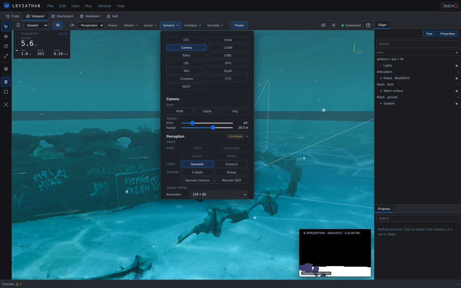
The live RGB, Depth and Seg modes are rendered by the Viewport's 3D view for display, using the camera's field of view and range. A PerceptionFrame is computed by the simulation service from the same camera pose. It is the scientific product, with declared units, frames, validity and identity, and it is the one exports and datasets use.
Camera geometry
The camera is a pinhole in the OpenCV optical frame: x right, y down, z forward along the optical axis. The field of view is horizontal. Intrinsics follow from the image size and that angle, with square pixels and pixel centres at integer coordinates:
For example, a 248 × 164 frame with a 90° field of view has f = 124 px and principal point (123.5, 81.5). The camera matrix K, the distortion model and the valid range interval (0, max range) are written into every frame's calibration record.
Lens distortion
Distortion is optional and follows the Brown–Conrady model on normalised coordinates (xn, yn), with r² = xn² + yn²:
The y component is symmetric. Under the opencv convention, a pixel is a distorted image point and its ray is undistort(K−1[u, v, 1]), as in OpenCV's calibration model. A legacy_v0 convention reproduces datasets made before PerceptionFrame. Inversion is iterative; motion products mark pixels outside the lens model's invertible domain as distortion undefined (see Surface correspondence).
Ground-truth channels
| Channel | Type | Units · frame | Meaning |
|---|---|---|---|
valid | bool | — | The ray hit geometry within (0, max range) |
semantic | uint16 | — | Canonical class id; open water is the water class; 65535 marks exact geometry with no semantic annotation |
instance | uint16 | — | Instance id from the frame's object table; 0 for water and seabed |
range | float64 | m · camera centre | Euclidean distance from the camera centre to the hit along the ray |
z_depth | float64 | m · camera | Distance of the hit along the optical axis |
normals_world | float64 × 3 | unit · NED | Surface normal, oriented toward the viewer |
normals_camera | float64 × 3 | unit · camera | The same normal rotated into the camera frame |
Semantic labels use a fixed marine vocabulary, which includes water, seabed, diver, plant, fish, reef, wreck, robot, ship hull, anode, bilge keel, propeller, sea-chest grating, marine growth, corrosion, defect, pipe, cable, manifold, wellhead, mine, debris, boulder, mooring and buoy. Each class has a fixed id and display colour, and common synonyms (for example rock, riser, fouling) map onto it.
Underwater image formation
The model is the revised underwater image formation model of Akkaynak and Treibitz (CVPR 2018). It separates the coefficient that governs direct transmission, βD, which depends on range, from the coefficient that governs backscatter, βB. The older atmospheric dehazing model uses one coefficient for both, and that is wrong underwater.
- Ambient illumination. Light from the sky arrives with an upper-hemisphere radiance distribution and is attenuated with depth. The irradiance on each surface depends on its depth and its viewer-oriented normal.
- Clean radiance. A Lambertian surface of reflectance ρ leaves radiance J = ρEn/π. This is
rgb_clean: the object as lit underwater, without the water between it and the camera. - Water transport. Along the ray of length r, the direct signal keeps a fraction t = exp(−βD(r)r), and the water adds single-scattered path radiance B. The radiance at the camera is I = J·t + B. This is
rgb_degraded, unclamped. - Sensor response. LEVIATHAN's normalised, quantised linear camera response turns radiance into a fraction of full scale. It has exposure (an EV value or automatic), knee, bit depth, read noise, shot noise and black level. This is
rgb_sensor, which is not a Bayer or RAW image.rgb_sensor_cleanis the clean radiance through the same exposure, without noise. - Display.
rgb_displayapplies the sRGB transfer function for viewing only. It is never ground truth, and it has its own identity hash.
| Channel | Units | Meaning |
|---|---|---|
albedo | — | Lambertian reflectance ρ of the surface hit; its source is recorded per object |
irradiance | E / Es | Ambient irradiance on the surface at its depth |
rgb_clean | sr⁻¹ (radiance / Es) | Clean surface-leaving radiance J |
transmission | — | Direct transmission t over the camera ray |
path_radiance | sr⁻¹ | Single-scattering water-path radiance B |
rgb_degraded | sr⁻¹ | Radiance at the camera, I = J·t + B |
rgb_sensor | fraction of full scale | Camera-response image with noise |
rgb_sensor_clean | fraction of full scale | Clean radiance through the same exposure, no noise |
rgb_display | sRGB [0, 1] | Visualisation only |
background, surface_not_modeled | bool | The ray looks into open water, or rises toward the sea surface without a hit |
radiometric_valid, radiometric_reason | bool, uint16 | Whether the pixel's whole radiometric chain is modelled, and if not, why |
Water types
Water is homogeneous and is specified by its beam attenuation coefficient c per colour channel, in m−1. You can pick a named type or give your own non-negative [r, g, b].
| Type | cR | cG | cB | Type | cR | cG | cB |
|---|---|---|---|---|---|---|---|
| clear | 0.42 | 0.09 | 0.03 | Jerlov II | 0.52 | 0.12 | 0.07 |
| coastal | 0.55 | 0.12 | 0.18 | Jerlov III | 0.64 | 0.16 | 0.12 |
| turbid | 0.88 | 0.30 | 0.45 | Jerlov 1C | 0.78 | 0.23 | 0.24 |
| murky | 1.90 | 0.90 | 1.20 | Jerlov 3C | 1.05 | 0.34 | 0.40 |
| Jerlov I | 0.34 | 0.07 | 0.021 | Jerlov 5C | 1.35 | 0.48 | 0.62 |
| Jerlov IA | 0.39 | 0.083 | 0.028 | Jerlov 7C | 1.75 | 0.68 | 0.90 |
| Jerlov IB | 0.44 | 0.095 | 0.038 | Jerlov 9C | 2.30 | 0.98 | 1.35 |
Ambient illumination
An ambient model is required: LEVIATHAN has no default, because the choice changes every radiometric value. Two models are available. A power-cosine sky has radiance proportional to cosm of the zenith angle, and you must state the exponent m. An isotropic sky is the case m = 0.
Outputs in the application
One capture produces every output from the same camera, pose and scene, so the channels line up pixel for pixel. Figure 4.4 shows five of them from a single Pipeline capture: the camera looks down at 32° over the manifold, the flowlines and a flanged pipe section, with coastal water and an isotropic sky.
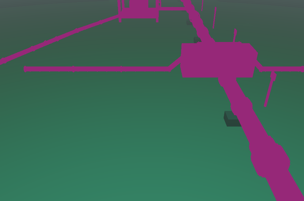
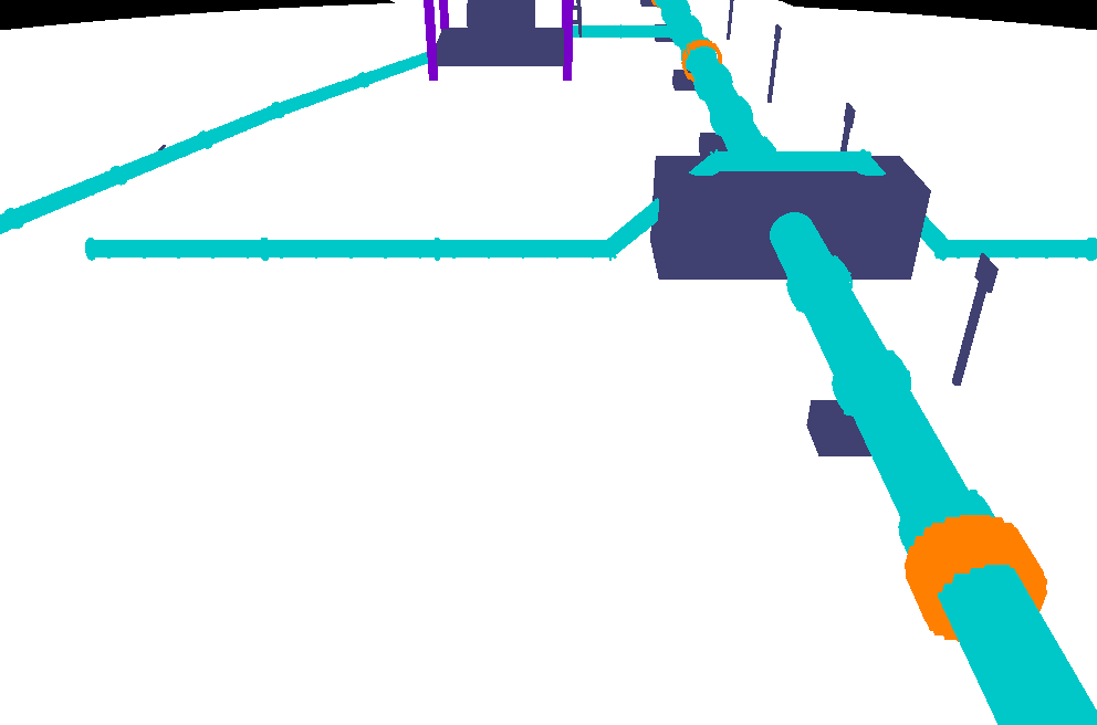
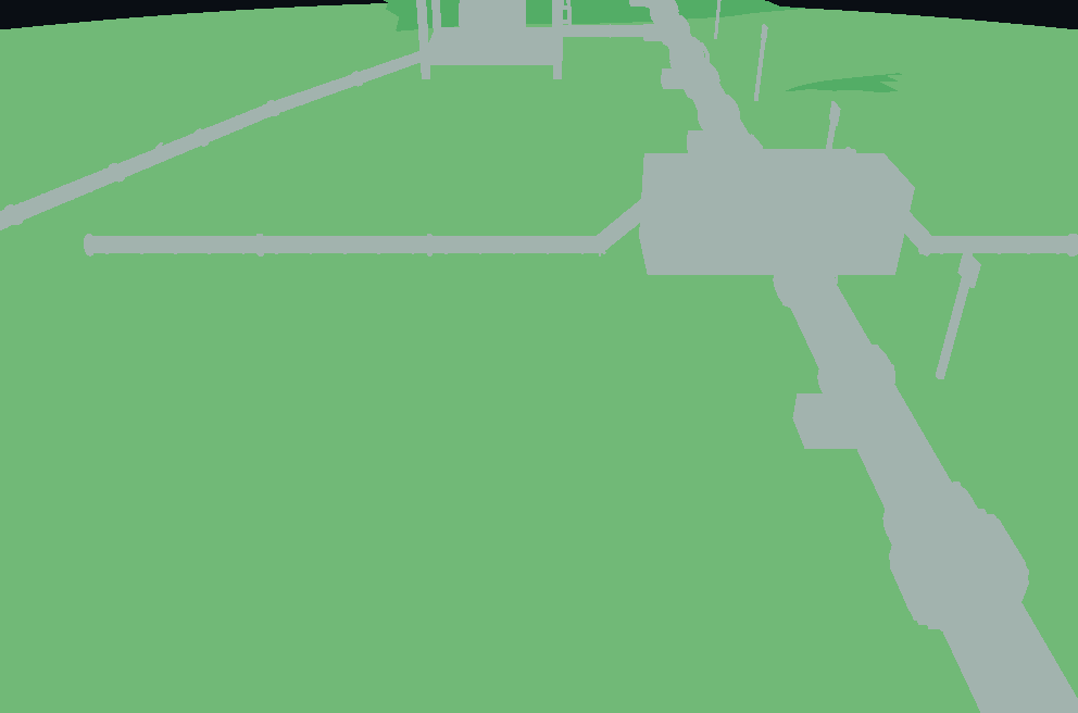
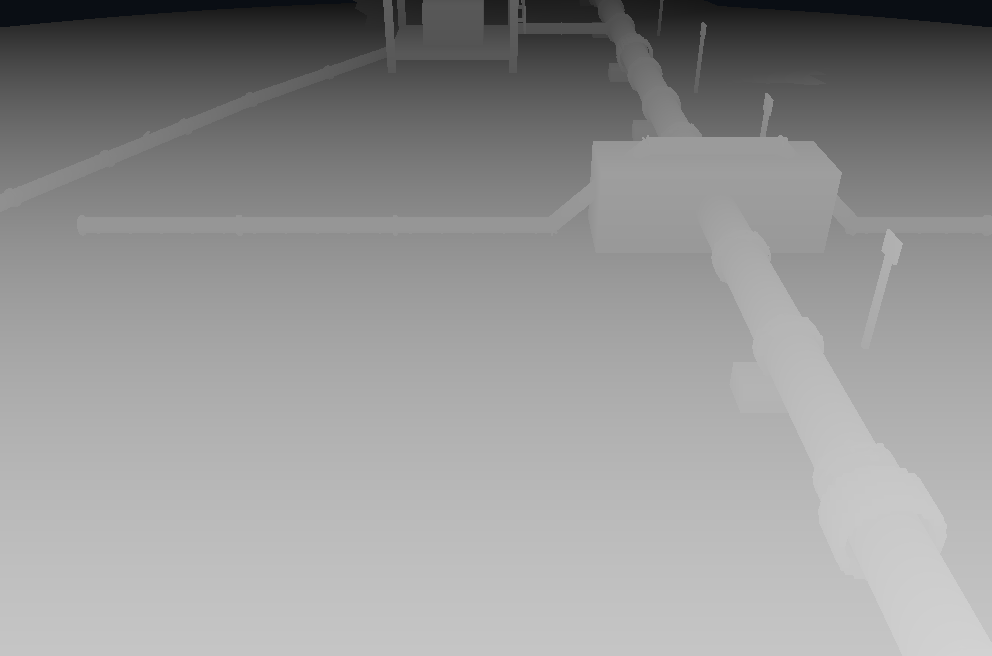
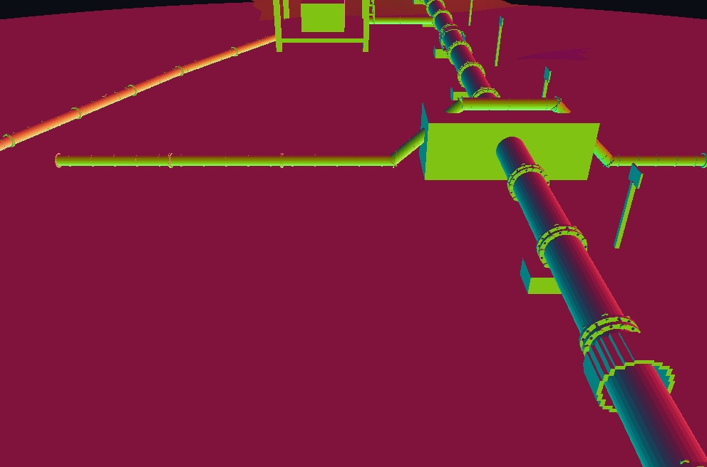
The same capture also holds the Clean, Sensor and Albedo images, Range, and normals in the NED world frame. Each is selected under Output in the camera panel and shown in the camera monitor.
Magenta in the image channels marks pixels without valid radiometry. The Pipeline structure's material map establishes reflectance only for its concrete pipe supports. The pipe, manifold, anodes and markers have geometry and labels but no established reflectance, so their radiometric reason is material_unknown. This capture used Estimated reflectance for the seabed, which the frame records as unmeasured.
Radiometric validity
A pixel's radiometry is reported only where every link of the chain is modelled. Otherwise the radiometric channels hold null, never a plausible-looking value such as black, and radiometric_reason records why:
| Code | Reason | Effect |
|---|---|---|
| 0 | valid | All radiometric channels present |
| 1 | material_unknown | No scientific reflectance: albedo, clean, underwater and sensor values are null |
| 2 | interface_crossing_unsupported | The camera-to-surface path crosses the air–water surface, which is not modelled |
| 3 | above_water_unsupported | The path or surface is in air; there is no topside illumination model |
Where reflectance comes from
Scene models carry display colours and textures, which are not evidence of how a surface reflects light. Reflectance is resolved in this order:
- an explicit reflectance given for the object;
- a material from LEVIATHAN's scientific material library, through a structure material map;
- only if you allow it, the display palette, recorded in the frame as an unmeasured estimate.
The scientific material library holds reflectances reduced from source spectra in the ECOSTRESS spectral library, currently a set of concretes. One built-in assignment exists: the pipeline site's concrete saddles. It is declared a proxy, because the values are dry-laboratory measurements not corrected for immersion. Every other surface is unknown until reflectance is supplied.
Completeness
Every frame states whether it is complete. When something physically present cannot be represented, the frame lists it with a category and a reason, and is marked incomplete. Examples are the ego vehicle, which is drawn by a display mesh only and has no scientific geometry, and entities without semantic labels. Omission categories include unsupported geometry, unsupported semantic labels, non-metric geometry, unsupported dynamic entities, unmapped entities, and participating media, illumination effects and interfaces that are not modelled.
Capture settings and limits
| Setting | Value |
|---|---|
| In-app resolutions | 124 × 82, 186 × 123, 248 × 164 (the feed's aspect) |
| Service limits | Up to 1024 px on a side and 65,536 pixels per frame; 16 frames and 262,144 pixels per dataset request |
| Scene objects | Spheres, boxes, meshes, mesh assets and structures; flat or absent seabed; up to 64 objects |
| Seed and frame index | Root seed and frame index; per-source random streams derive from them |
| Arrays | IEEE-754 binary64, unrounded |
Direct sunlight, artificial lights, the sea surface (reflection and refraction), multiple scattering, forward-scatter blur, ambient light varying along the ray, discrete suspended particles and stratified water. Pixels that depend on these are marked rather than approximated.